I have become quite enamored of TeX’s ability to let me write what I mean and have the computer get the syntax right. LyX calls this “What You See Is What You Mean.”
Cross-references With Containers
I occasionally want to produce something like “Example 4 (in Section 1.2.3)”.
Fortunately, I am in the habit of using cross-reference labels that have
hierarchy to them, a la type:level1:level2:...:levelN, with type
being something like fig or sec. Thus, to get from
exa:foo:bar:baz:quux to sec:foo:bar:baz requires stripping off the
last :levelN and replacing the type exa with sec. Using
xstring and a little pain we can count the number of colons in the label
and cut the string apart appropriately, and use cleveref and
hyperref to do their thing:
\makeatletter
\newcommand*{\@crefin}[4]{%
  \StrCount{#4}{#3}[\cnt]%
  \@tempcnta=\numexpr\cnt-(#2)\relax%
  \StrBefore[\the\@tempcnta]{#4}{#3}[\ctnr]%
  \ifstrempty{#1}{}{\StrBehind[1]{\ctnr}{#3}[\ctnr]\preto\ctnr{#1#3}}%
}
% Refer to something in its container: "X (in Y)" where Y's reference
% strips off n+1 segments from the delimited name for X, using : as the default
% delimiter and replacing the first with some other type, "sec" by default.
% Use as \crefin[ty][n]<:>{some:structured:ref}
\NewDocumentCommand{\crefin}{ O{sec} O{0} D<>{:} m }{%
  \bgroup\@crefin{#1}{#2}{#3}{#4}\hyperref[#4]{\cref*{#4} (in \cref*{\ctnr})}\egroup%
}
% Refer to something in its container: "``X'' (in Y)" where Y is computed
% as with \crefin above.
\NewDocumentCommand{\namecrefin}{ O{sec} O{0} D<>{:} m }{%
  \bgroup\@crefin{#1}{#2}{#3}{#4}\hyperref[{#4}]{``\nameref*{#4}'' in \cref*{\ctnr}}\egroup%
}
\makeatother
Sometimes, the referenced object does not have an overt number, such as
(sub)paragraph headings. In that case, the \namecrefin command which
will use the heading name itself, rendering as “Some Topic (in Section 4)”.
Prettier Subscripted Quantifiers
I like to subscript my quantifiers (and occasionally superscript some of
them). I know, I’m weird. Anyway, I find that a subscripted universal
quantifier really wants some kerning, and for uniformity, I went and defined
commands for the rest of the ones I use. Thus, using xparse:
\let\existsord\exists
\let\forallord\forall
\let\Piord\Pi
\let\Sigmaord\Sigma

\makeatletter
  \newcommand*{\forallargs}[1]{\IfNoValueF{#1}{_{\mkern-4mu{#1}}}}
  \RenewDocumentCommand{\forall}{e{_}}{\mathord{\forallord\forallargs#1}\,}

  \NewDocumentCommand{\subsuper}{m g}{\IfValueT{#1}{\ifstrempty{#1}{}{_{#1}}}\IfValueT{#2}{^{#2}}}
  \RenewDocumentCommand{\exists}{t! e{_}}{\mathord{\existsord\IfBooleanTF{#1}{!}{}\subsuper#2}\,}
  \RenewDocumentCommand{\Sigma}{e{_}}{\mathord{\Sigmaord\subsuper#1}\,}
  \RenewDocumentCommand{\Pi}{e{_^}}{\mathord{\Piord\subsuper#1}\,}
\makeatother
You may find that your collaborators are not using sufficiently recent
versions of xparse; in which case, putting
\@ifpackagelater{xparse}{2016/11/20}{...}{} around the indented code (as
...) will make it compile but uglier for them.
Colored Math Grouping Symbols
Who doesn’t like colors? Using xcolor and xparse we can define
commands to get us colored angles:
\definecolor{verylightgray}{rgb}{.8,.8,.8}
\definecolorseries{canglescs}{rgb}{grad}[rgb]{.95,.85,.55}{3,11,17}
\resetcolorseries[12]{canglescs}

\DeclarePairedDelimiterXPP\cangles[1]
  {\colorlet{canglesc}{canglescs!!+}}
  {\bgroup\maskcolors[rgb]{verylightgray}\color{canglesc}\langle\egroup}
  {\bgroup\maskcolors[rgb]{verylightgray}\color{canglesc}\rangle\egroup}
  {}
  {#1}
Drawing Nice Hyperedges with Tikz
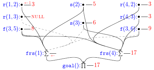
In my work on Dyna, I very often needed to draw directed B-hypergraphs. When drawing by hand, I almost invariably use (IMHO) nice, swooped arcs that join smoothly together. But the TeX tools like to draw straight lines, which result in bird-track-like hyperedges, which look pretty bad. Keep reading if you like pictures like this:

TikZ/pgf, however, can do some amazing things. For my current paper, which
uniformly draws circuits where sources are closer to the top of the page
than targets, I have defined a \fhe macro (“fancy hyper edge”) using the
xparse and tikz packages (and the calc and fit tikz
libraries). Assuming you have the appropriate analog of
\usepackage{xparse}
\usepackage{tikz}
  \usetikzlibrary{calc,fit}
in your preamble, then hyperedges.tex will get you what you
want. This produces a series of curves from each source point to a “crux” where
they all meet. In order to get the curves to look nice, a “precrux” is
defined nearby and used in a control point calculations for these curves.
By default, the precrux is computed by averaging the source positions and a
heavy bias towards the target point. It is, however, adjustable by
argument, in case the default doesn’t work out well for you. The crux is
then the midpoint of the precrux and target; all the curves from the source
converge here and a single line extends to the target.
As can be seen by the core \foreach loop, the hyperedges are drawn as
curves from each source to the source-precrux midpoint to the crux, using
some computed points to make things look pretty.
The parser directives produce a command that takes six arguments:
TikZ edge directives, optional, in square brackets
[]. Useful mostly for coloring.TikZ directives for the crux node, optional, in angle brackets
<>. This is the tail of adrawTikZ directive, so is very powerful. Useful for putting bullet points or such at the crux, as in<{{\ensuremath\bullet}}>(The two layers of braces are necessary for TikZ labeling as the outer set are eaten by argument handling.), or for things nearby as in<{[left] {label}}>.A TikZ coordinate expression, including possibly a calc expression, for redefining the
precruxpoint, optional, in square brackets[]. Note that the TikZ coordinatestargetandprecruxare in (TikZ) scope for this adjustment, (as is the TeX definefhe@midpoints, though that is far less likely to be useful); this is especially useful if you just want to push the crux closer or further from the target by default. Note that if this is being used and neither of the above optional arguments are used, it is still necessary to provide an emtpy<>to distinguish this from the first argument.The single target node TikZ coordinate, mandatory, curly braces.
A comma-separated list of source node TikZ coordinates, mandatory, curly braces.
The use of \begin{scope} and \end{scope} results in none of the
internal coordinates (crux, precrux, and target) being visible
after the command completes.
All told, this lets me write things like the following:
\fhe{frs1.north}{r12.south,s2.south,f35.south}
\fhe[gray,dashed]{frs1.north}{r13.south,s3.south,f36.south}
\fhe<>[$(target)+(-.1,.1)$]{goal.north}{frs1.south}
to define three of the edges (the grey dashed one and the ones below it and to its left) in pictures like the one up top.